Week 16: System integration
The assignment:
2. Individual assignment: Design and document the system integration for your final project
For this week we have to lay out a plan for how the final project is integrated as a system and how I will make it look good and finished. A sketch of the idea in total:
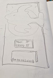
The visualization (the fish), the LCD and the box with the PCB are all mounted on a piece of plywood or other suitable material as a base. The wiring goes on the backside of the plywood. The PCB is also connected to the internet and the data (humidity an temperature) is logged in a Google spreadsheet.
Here is an overview of the single parts that I have made for my final project until now:
There are 2 main categories:
The electronics and the packaging of it:
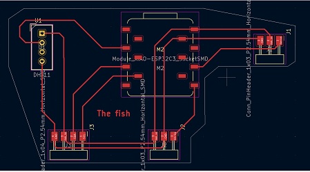
In the KiCAd PCB editor you can see the connections to the board:
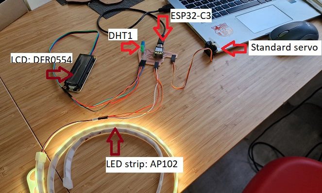
When I connect the electronics accordingly and lay the electronics out on the table it looks like this:
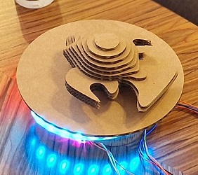
For packaging I have made a first prototype of possible enclosure. It consist of a rounded lasercut box and a circle.
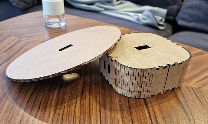
The servo is going through the holes and the LED strip is attached to outside of the rounded box. The circle should give a kind of backlight effect when the LEDs are turned on.
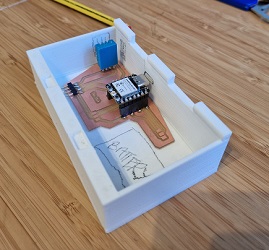
The PCB itself is going underneath it all in a 3D printed enclosure of its own. I should be accessible so a user can open it easily. The ESP32-C3 is powered by a batterypack so there must be room for that as well. For now I have made a simple box to test it
The LCD is mounted directly on the plywood base.
The design and manufacturing of the visualization:
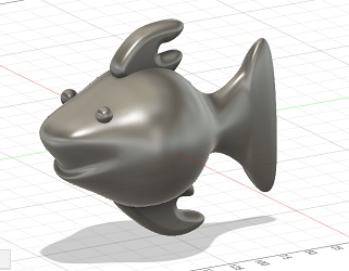
For visualization I have chosen a fish. I have designed a few in Fusion360 and this version is the prototype that I work with at the moment:
I have cut the model as stacked slices out of cardboard. Assembled in halfsize it looks like this:
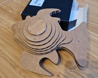
For the next version I will try to scale it up a bit and cut it in plywood. My concern is that it might get to heavy. These small standard servos have a stalled tourque of approx.: 3,3 kg/cm. That means that the servo motor will stop rotating when it is trying to move a 3,3 kg weight at a radial distance of 1.0 cm.
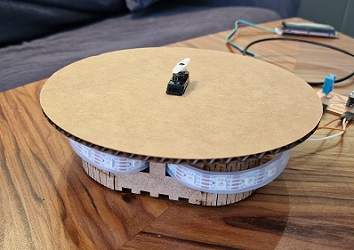
A simple test of the backlite looks like this: